|
Vivoe Lite 0.5.0
Lightweight GVA like HMI for military displays.
|
|
Vivoe Lite 0.5.0
Lightweight GVA like HMI for military displays.
|
This documentation was created from git hash #$(GIT_HASH)
You can build vivoe-lite from source (See section on Building) or install from the pre build binaries on our website here.
Once installed the executable should be part of your PATH and can be ran from anywhere (/etc/profile.d/vivoe-lite.sh), if you have issues you can run with the full path:
For help you can list the options using:
For instructions in installing vivoe-lite binary packages please refer to the Developer SDK section.
This VIVOE (Vetronics Infrastructure for Video Over Ethernet) environment is currently tested on Ubuntu 22.04 LTS. Please ensure you have the following packages installed prior to building the application:
And install these additional packages to build the documentation:
On CentOS there are a few additional repos required for the software to build these are epel-release and powertools, below are the settings to set these prior to installing the dependencies
Once the repos are updated install the following packages.
And install these additional packages to build the documentation:
Cross compilation for Windows systems is achieved using MSYS2 (https://www.msys2.org/). Using the pacman package manager you can install all the required dependancies:
To build the windows Nullsoft (https://nsis.sourceforge.io/) installer cpack from your build directory:
This project has a couple of options that can be specified at compile time:
Default DDS stack is currently CycloneDDS (default if not specified) but can also be built with Opensplice by setting -DDDS=OSPL-CE.
To enable code coverage reports set ENABLE_COVERAGE. The gdb debugger is avaiable and configured for use with Microsoft Visual Code and the workspace files are part of the repo (recommended for developers).
The BMS function can be configured with Open Street Maps but these need to be compiled and installed onto the system. Its recommeded that you run wit these switched off if you do not need this functionality. See below for more information on creating maps for your region / territory.
Once the code is built the required files should be installed. There are two method for getting the files to their install locations. Firstly with cmake run:
Secondly you can create the platform specific install bundle and install that.
If you wish to start working with this code base then this section provides guidance for developers. The build system is CMake and you should have a good understanding of the CMake build system before station to add code into this reop.
The project to broken down into modules and submodules these can be seen in the diagram below:

If you are usings the software control for screen brigtness then please ensure that the file /sys/class/backlight/intel_backlight/brightness is setup to control the backlight. Brightness functions will only work if the application is run with superuser permissions, if run as normal user then the brightness will not work and an error will be logged.
To manually set the brightness from the command line run:
Sets the brightness to 100%.
To get a detailed view of whats going on in the code you can enable Linux Test Trace (See https://lttng.org/). This is enabled using the CMake macro shown below:
Once built you can run with trace using the trace script in /scripts as shown below (from the build directory):
Trace files are now available in the defaullt location (normally $HOME) or in the directory poited to by $LTTNG_HOME/lttng-traces.
The recommeded GUI for viewing traces is trace compass by the Eclipse foundation. Tool can be downloaded here https://www.eclipse.org/tracecompass/
Import the trace and select the trace directory File -> Import. While importing select Create Experiment and set the log file type to Common Trace Format: LTTng UST Trace. At this point you can click ** Finish** to import.
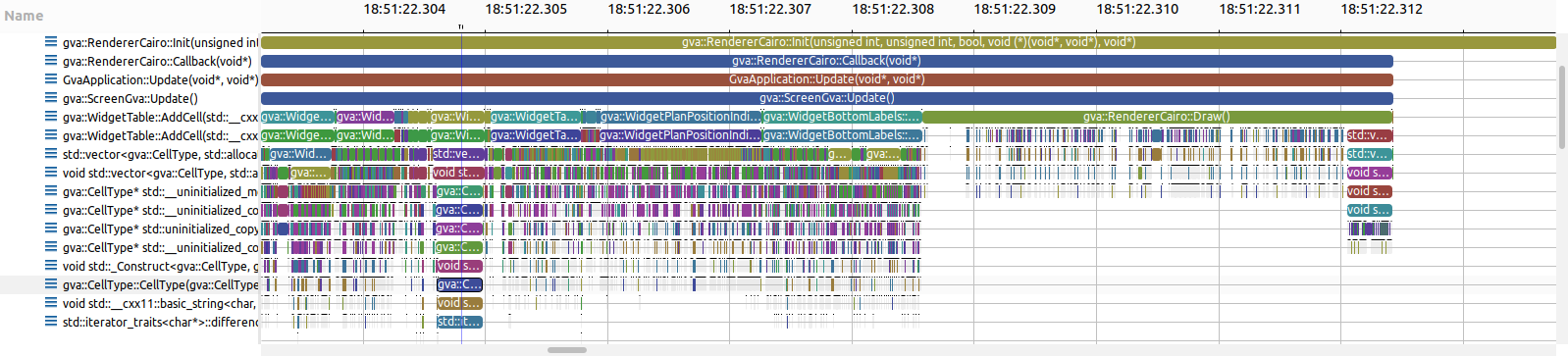
Once imported you can open the experiment and view the interactive flame graph as shown below:
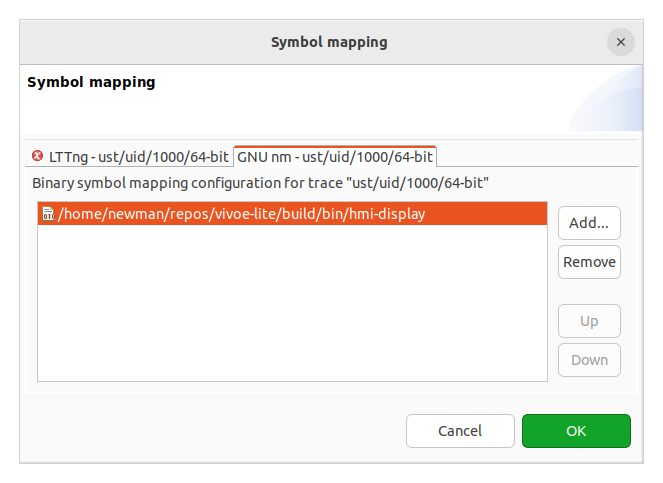
You may see raw addresses. To resolve the function names click![]() and point to the binary executable:
and point to the binary executable:
You can create this documentation on your own system using doxygen. It is recommended that you run the cmake target to handle the macro replacements for version information as shown below (in the build directory)
Images included in the documentation are autogenerated using the Widget Tester it is not recommended that youi run doxygen directly from the command line. If you do want to run doxygen directly then you will need to manuall specify the environment variables as shown below:
To generate the images needed for doxygen then run the widget tester as sown below:
This will produce all the imagery needed for all the widgets currently supported. Images are .png files and contain transparency, these can be further cropped using the convert command below.
This needs to be done for every image. All handled in the make doxygen target.
There are built in graphical elements that can be animated and extended to meet your requirements some of these are shown below.
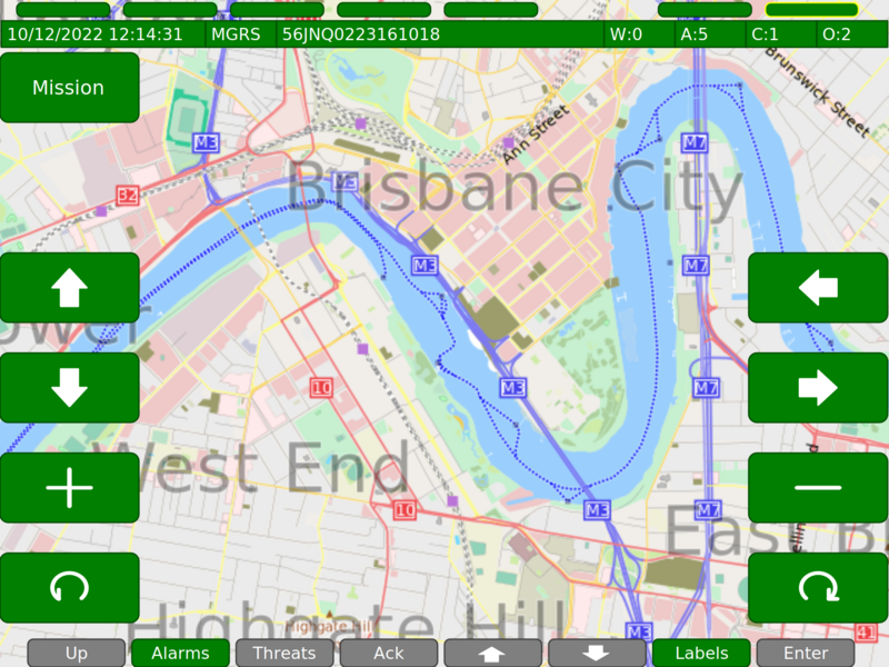
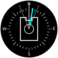
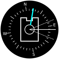
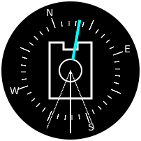
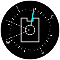
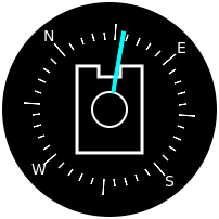
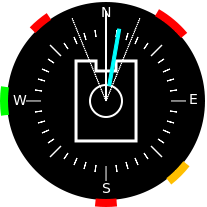
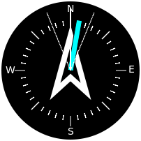
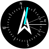
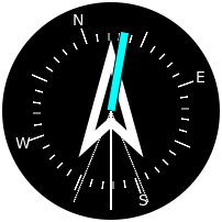
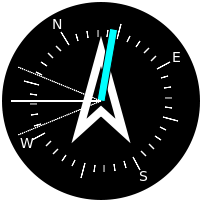
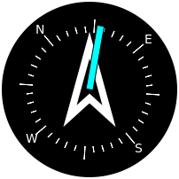
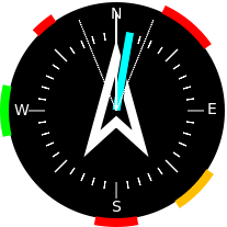
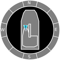
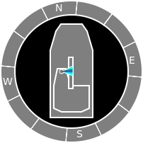
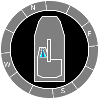
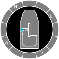
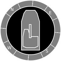
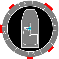
The PPI comes in servral modes, see gva::WidgetPlanPositionIndicator.
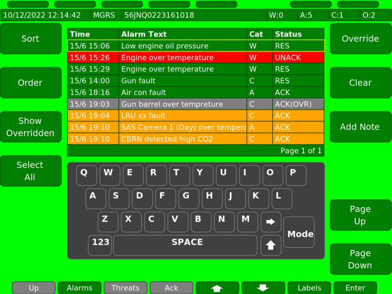
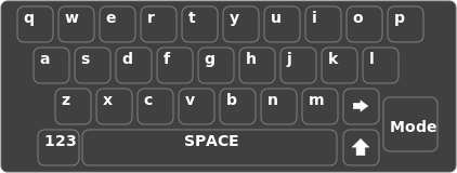
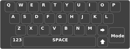
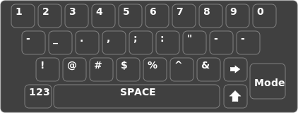
The keyboard has servral input modes, see gva::WidgetKeyboard.
The alarms states are displayed as follows, see gva::WidgetAlarmIndicator.

Note the advisory state will take the current theme background.


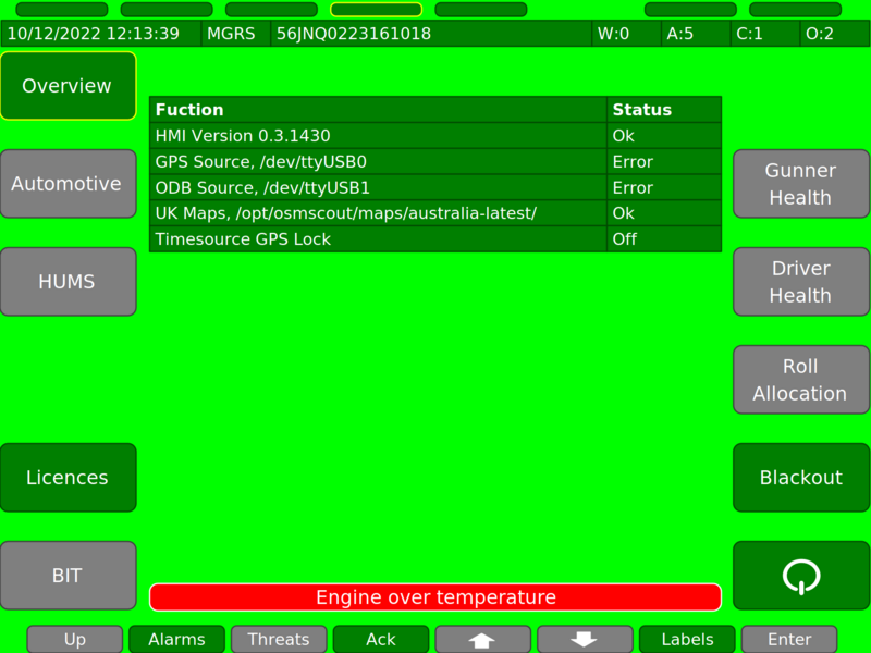
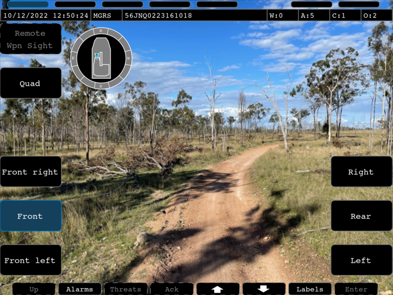
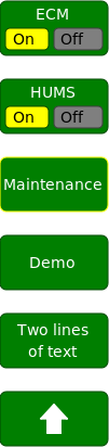
The functional area states are displayed as follows, see gva::WidgetTopLabels.

The control states are displayed as follows, see gva::WidgetBottomLabels.

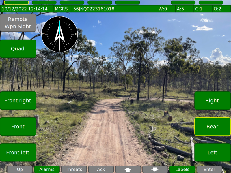
The label states are displayed as follows, see gva::WidgetSideLabels.
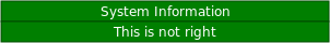
A mode example can be seen below gva::WidgetMode. It is a GVA requirement that the operator is informed when the system is not operable due to maintinance.

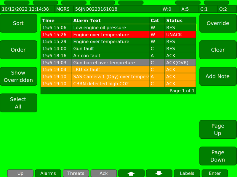
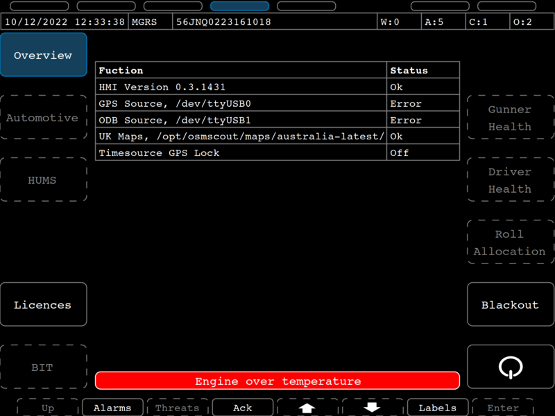
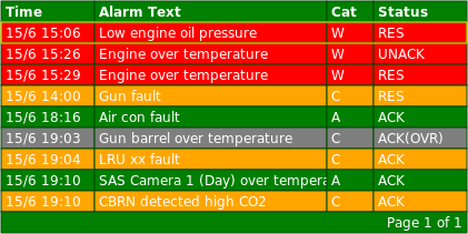
A table example example can be seen below gva::WidgetTable, add rows and cells as required these can be colour coded and highlighted for interactive table.
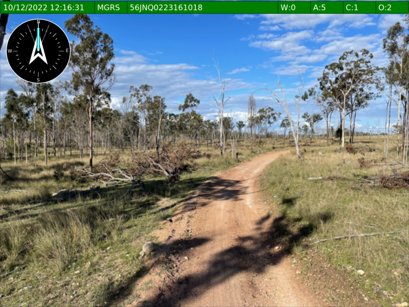
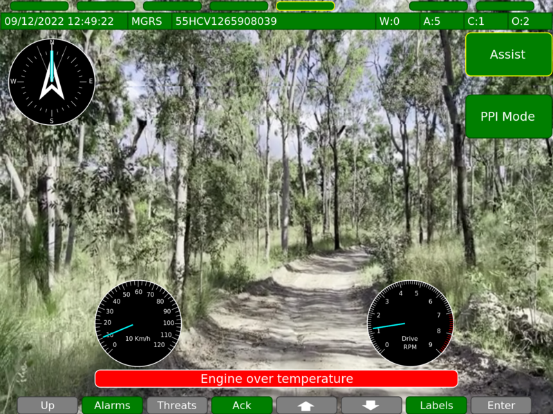
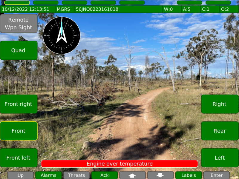
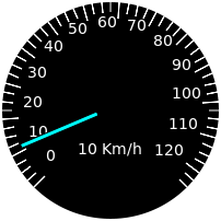
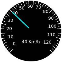
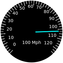
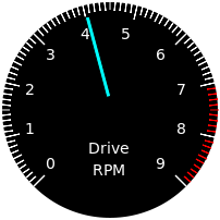
The driver has some special widgets for operating the vehicle the speedometer gva::WidgetDriverSpeedometer is overlaid over the drivers camera.
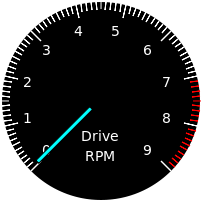
The driver has some special widgets for operating the vehicle the RPM and Fuel gauage gva::WidgetDriverRpmFuel is overlaid over the drivers camera.
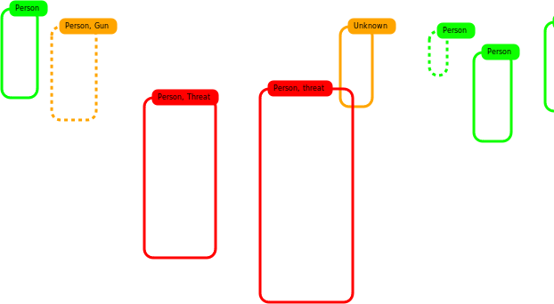
This overlay is used with AI networks to highlight regions of interest.
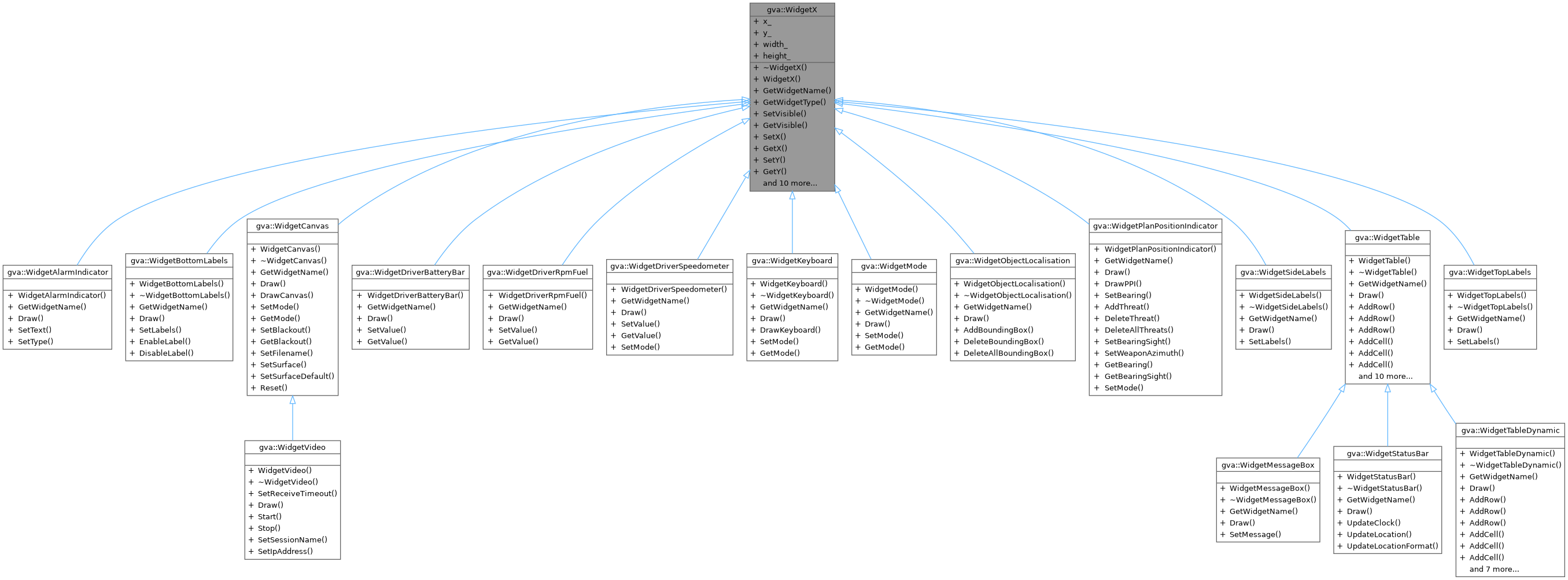
When creating new widgets it is advisable to add tests for the widget element. All widgets are derived from the gva::WidgetX base class. The simplest widget being the gva::WidgetMode which can be used as a basic example of how to create a new widget.
The test program widget-tester.cc can assist you in testing your new widget without needing to build the entire HMI. This tester is also used to autogenerate the imagry used in this documentation See Documentation
Widgets can then be rendered and viewed using the widget-tester.cc console program. The current widgets built into the SDK are shown below:
To simplify the processing of maps for some countries a bash script is provided in the scripts/maps folder called scripts/maps/process_maps.sh. Currently three countries are processed with this script and these are:
Please feel free to modify the script to process the country/s you require. For convinience processed map archives are avaliable from the defencex.com.au website in the downloads area. These are updated on an adhock bases for testing purposes.
Once you have created your maps you will need to poit the config file at the map install location. Please edit and rebuild the config.proto file to point to you install location (osm.map_path).
Find you maps over on http://www.geofabrik.de/
OSMScout import guide https://libosmscout.sourceforge.net/tutorials/importing/
The default install locations for maps is under /opt below shows the sugested layout:
To achieve this configuration with the archived maps run the following commands as superuser: